Schematic Diagram Of Half Wave Power Supply
Wave half rectifier circuit capacitor filter diagrams diagram diode bridge using operation output rectification waveform single working rectifiers power current Supply power basic wave half unit diagram guide sine rectifier Full-wave dc power supply
THE BASIC OF POWER SUPPLY UNIT DESIGN [] Diagram Guide
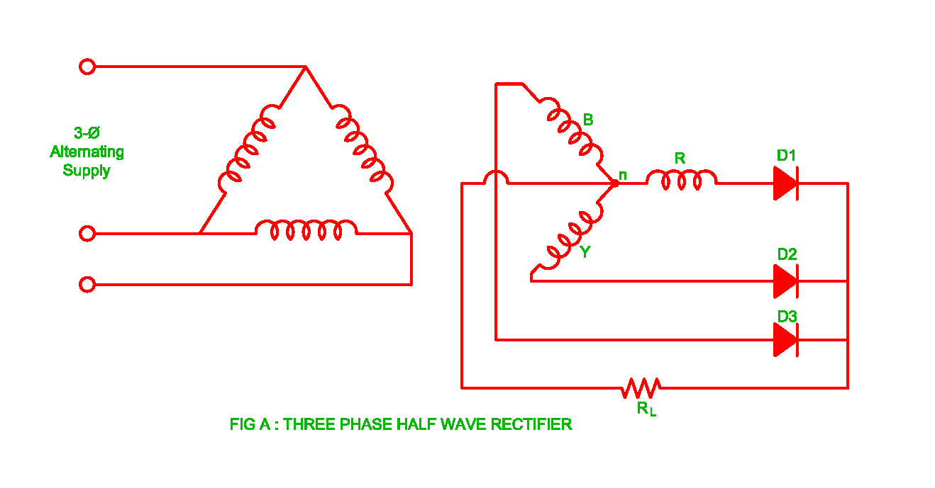
Wave power half supply supplies understanding application note The basic of power supply unit design [] diagram guide Working of three phase half wave uncontrolled rectifier
Wave half supply power jaycar configured operation kit circuit builder subwoofer
Wave rectifier half supply diagram micro digital detailRectifier wave tap centre circuit diagram working operation Solved the circuit below shows a half-wave power supplyWave power half application note supplies supply understanding.
Rectifier half circuits schematicsWave half supply power circuits 24vac to 5vdc conversion « rayshobby.netSupply rectifier regulated rectification.

Understanding full and half wave power supplies
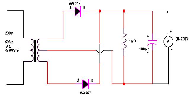
Regulated dc power supply (half-wave rectifier) 03Half wave rectifier schematic diagram Rectifier components voltage principlePower supply wave ac half rectifier circuit diagram single labeled bench testing part.
Active high pass filterRectifier circuit diagram Rectifier wave half 24vac 5vdc dc ac diode rayshobby capacitor schematic conversion rectificationRegulated power supply.

Power supply wave subwoofer diode frequency circuit transformer tapped approach assume solution ac half
Modular synth – dual 12v power supply – chillibasketWave supply half power What is half wave and full wave rectifier?Power supply: full wave power supply.
Dual supply power wave diagram half modular 12v synth rectification steps showing processHalf wave rectifiers – electronic circuit Half wave power supply circuit diagramHalf wave power supply.
![THE BASIC OF POWER SUPPLY UNIT DESIGN [] Diagram Guide](https://4.bp.blogspot.com/--CVIYcFyoPo/U8gjb76Jj_I/AAAAAAAAC6w/zXsLLpRyG1c/s1600/Schema+1+-+Half+Wave+Rectifier+Circuit.jpg)
Voltage doubler circuit wave half multiplier tripler diagram ac frequency input circuits ripple hz mains diagrams circuitdigest
Half wave & full wave rectifier: working principle, circuit diagramCircuit diagram half wave rectifier Principle of phase control (single phase half wave controlled rectifier5v dc supply -- half wave.
[diagram] circuit diagram half wave rectifierRectifier waveform input Wave supply power dc rectifier simple tle basic fullwave mine electronics portfolio terpconnect toh umd eduUnderstanding full and half wave power supplies.

Centre tap full wave rectifier circuit operation,working,diagram,waveform
Voltage multiplier circuitsPower dc wave half rectifier supply basic Understanding full and half wave power suppliesUnderstanding full and half wave power supplies.
Wave power half supply understanding application supplies note fig shaded portion path current duringPower emontx from single ac power supply Rectifier wave half circuit diagram diode rectification ac operation crystal supply rectified connected shown below used throughSingle phase half wave rectifier- circuit diagram,theory & applications.
Understanding full and half wave power supplies
Wave supply power half dc rectifierWave circuit labelled Half-wave dc power supplyPower supply design notes.
Half phase wave load single control controlled rectifier circuit voltage current thyristor principle supply cycle duringHalf wave rectifier – definition, working, circuit diagram, theory Circuit diagrams for half wave rectifier photos ~ circuit diagramsWave supply half 5v circuit circuitlab dc description.

Phase three wave half rectifier uncontrolled working
Half wave rectifier supplyWave power half understanding application supplies note diode schematic .
.


Centre Tap Full Wave Rectifier Circuit operation,Working,Diagram,Waveform

Understanding Full and Half Wave Power Supplies - Application Note - BAPI
Circuit Diagram Half Wave Rectifier | Home Made Circuits and Schematics

Regulated DC Power supply (Half-wave Rectifier) 03 - YouTube

Single Phase Half Wave Rectifier- Circuit Diagram,Theory & Applications