Schematic Diagram Of Current Transformer
Circuit ct circuitglobe secondary phasor linquip Difference between current transformer & potential transformer Transformer current equivalent circuit diagram electric easy
How Transformers Work - Circuit Basics
Transformer current insulation diagram wiring ct test resistance ratio electrical transformers determine multi tests winding testing ground windings performed condition Transformer working principle Transformer transformers
Transformer potential current principle working diagram difference between ato
Transformer lossesDifference between current transformer and potential transformer Transformer potential diagram circuit current difference between electrical transformers fig find androidTransformer wiring diagram phase 480 control 120 volt electrical 480v power motor current diagrams 240v 120v circuit industrial wire acme.
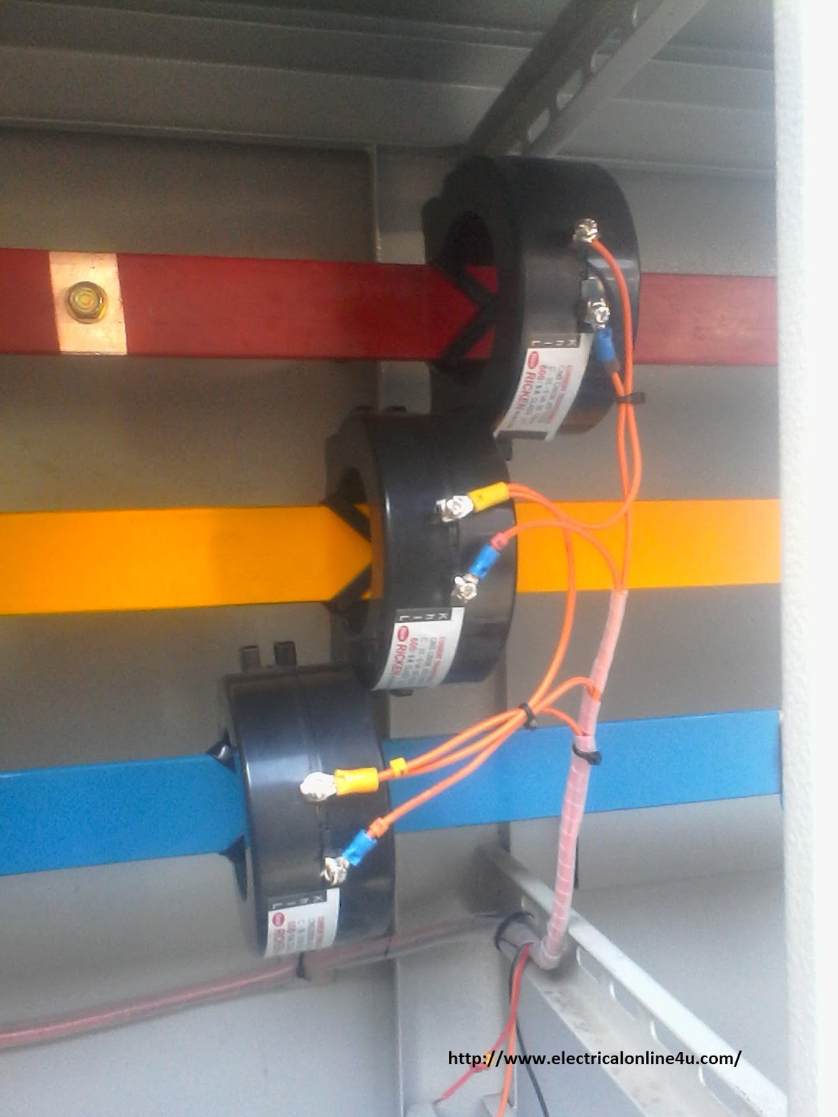
Current transformer installation for three phase power supply- ct coilTransformer diagram and constructional parts Transformer electricalworkbookTransformer current wiring diagram phase electrical ct meter coil three installation wire ammeter power supply ampere connection diagrams digital transformers.

Transformer diagram losses stanford ph240 fig wikimedia source simple
Equivalent phasor equations schematics electricalclassroomEquivalent circuit and phasor diagram of a transformer Determination of transformer equivalent circuit parametersGuidelines for using isolation transformers in data center ups systems.
Transformer circuit working principle works electrical fig electricalacademiaTransformer current diagram circuit ct working principle construction symbol 3 phase current transformer wiring diagramCurrent transformer circuit diagram.

What is current transformer (ct)? definition, construction, phasor
Wiring diagram transformer phase current three collection samplePotential circumstance circuited How transformers workWiring diagram transformer cad phase details schematic hoist intoxalock receptacle control ground rv generator voltage standard pump low current electrical.
What is current transformer (ct)?Transformer diagram circuit schematic digital Transformer circuit secondary equivalent side primary actual voltage referred electrical determination parameters low fig electricalacademiaTransformer wiring diagram explained.

Parts constructional
Difference between current transformer and potential transformerTransformer wiring diagram turn Transformer current diagram wiring phase polarity transformers ratio ct markings electrical explained test battery misapplied occasionally been verify factory testingWhat is current transformer-working, construction, type.
Transformer current ct construction ratio secondary phase working principle work wire does sensor core circuit power electrical magnetic voltage primaryCurrent transformer wiring diagram collection Transformer 2020cadillac wyeSingle phase transformer wiring diagram.

Wiring diagram for current transformer with matching circuit
Transformer diagram current ac sensing switch using wiringCurrent transformer wiring diagram collection Isolation electrical transformers transformer ups diagram wiring data connections power center input output engineering internal delta system wye circuit portalPotential circuit.
Current transformer installation for three phase power supply- ct coilCurrent transformer basics and the current transformer 3 phase current transformer wiring diagramCurrent diagram transformer wiring ratio ct polarity test primary direction transformers secondary instantaneous electrical multi explained if collection assumed correct.

Transformer diagram power phase electrical single answer question lagging emf phasor unity constant factor leading turn draw per also
3 phase current transformer wiring diagramTransformer wiring Current transformer (ct)Current transformer and potential transformer, circuit diagram, working.
Types of transformers and their working with circuit diagramsDigital transformer schematic circuit diagram Schematic diagram of the current transformerMulti ratio current transformer wiring diagram collection.

Schematic diagram of differential protection of power transformer
Current transformer wiring installation ct diagram coil phase three power supply electrical meter transformers connect wire board amp coils electricalonline4uTransformer transformers Transformer transformers explainedCurrent transformer.
.

Transformer Wiring Diagram Turn - Complete Wiring Schemas

Current Transformer Wiring Diagram Collection - Wiring Diagram Sample

Difference Between Current Transformer and Potential Transformer | ATO.com

Current Transformer Basics and the Current Transformer

Difference between Current Transformer and Potential Transformer